|
Article ID: 911
Last updated: 20 Mar, 2019
The Riva synchronization solution can be deployed using several different configurations. For information about the types of network topologies to consider and details about local and remote mail files, see these topics: Planning Your Network TopologyThese topics describe three different network topologies and give more specific information about why each might be used:
Direct connectionThe Riva Sync Connector for IBM Notes server in installed on a server inside your DMZ. The server should not contain any user mail files. The Riva Sync Connector provides the communication gateway between the Domino/Notes server(s) and the Riva Sync Service. The Riva Sync Service can be installed on one or more servers in your environment, or the Riva Sync Service can be provided by Riva Cloud. This topology is recommended for most Riva On-Premise and Riva Cloud deployments. Note: The diagram below shows using only HTTPS (SSL) connections between the endpoints. While it is technically possible to connect using HTTP (port 80), this configuration is not recommended.
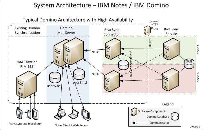
Fault-tolerance using native Domino replicationThe Riva Sync Connector for IBM Notes software that is installed as a Domino database supports native Domino replication allowing for high-availability if a server becomes unavailable. The following diagram illustrates the logic components of a multiple server deployment scenario to provide high-availability of the Riva synchronization solution. In this diagram, the logical placement is illustrated, not the physical placement. The components depicted in NODE A and NODE B can be (although not required to be) installed on the same logical Windows system (virtual or physical).
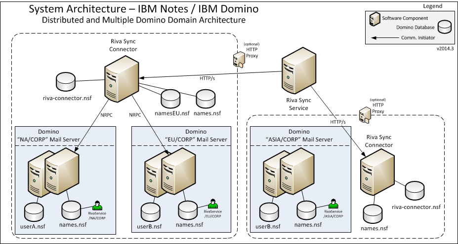
Distributed and multiple Riva sync connectorIn cases when a WAN link causes degraded performance, it may be beneficial to deploy a Riva Connector local to the network on which the mail servers are running. By adding a local Riva Connector, the number of remote Notes RPC requests that must cross the WAN is reduced and results in greatly improved performance and decreases synchronization cycle durations. In this diagram, the logical placement is illustrated, not the physical placement. The components depicted may be (although not required to be) installed on the same logical Windows system (virtual or physical).
Article ID: 911
Last updated: 20 Mar, 2019
Revision: 3
Views: 6751
Also read
|
.png)


